Traceability dictates the rhythm of modern electronics manufacturing. A single unreadable barcode halts production lines, compromises quality control, and violates strict compliance standards. The harsh realities of Surface Mount Technology (SMT) and Printed Circuit Board assembly demand robust identification. Standard labeling solutions degrade quickly. They melt, warp, or detach when exposed to lead-free reflow temperatures. Wave soldering and aggressive chemical cleaning agents destroy conventional materials.
Selecting the correct circuit board labels requires a systematic evaluation of face stock materials, adhesive formulations, printing technologies, and automation compatibility. You must engineer a solution that survives the entire manufacturing lifecycle. This approach guarantees end-to-end traceability, ensuring every board can be tracked from bare FR-4 through final assembly and into the field.
Material Durability is Non-Negotiable: Polyimide is the industry standard for surviving reflow and wave soldering temperatures (up to 300°C), while polyester is restricted to post-process or low-heat applications.
Print Method Dictates Readability: Only thermal transfer printing with high-durability resin ribbons can withstand the abrasion and chemical washes inherent in PCB manufacturing.
Automation Drives Efficiency: Labels must be engineered on specific release liners to integrate seamlessly with auto-apply SMT label feeders and pick-and-place equipment.
Compliance Mitigates Risk: Selecting UL-recognized, RoHS-compliant, and ESD-safe labels prevents regulatory bottlenecks and protects sensitive components from electrostatic discharge.
The Operational Realities of PCB Traceability
A successful labeling strategy hinges on strict performance metrics. Manufacturers require 100% barcode scan rates post-assembly. Any drop in scan rates forces manual intervention, triggering rework loops and slowing throughput. Zero adhesive residue on critical components prevents electrical shorts and signal interference. Permanent adhesion through the product lifecycle ensures accurate warranty tracking and field service identification. Achieving these metrics requires materials engineered specifically for extreme manufacturing environments.
Lead-free reflow soldering pushes boards through intense heat zones. The thermal profile of a standard SMT line is brutal on synthetic materials. Boards enter a pre-heat zone to activate the solder paste flux, soaking at 150°C to 200°C for up to two minutes. The board then ramps up to the peak reflow zone. Temperatures routinely peak between 245°C and 260°C, sometimes touching 300°C for short durations. The transition between ambient temperatures and peak reflow creates severe thermal shock. Standard paper or basic synthetic materials ignite, melt, or shrink violently under these conditions. The label face stock must maintain complete dimensional stability to keep printed barcodes readable.
Chemical and mechanical stressors further complicate traceability. Post-solder cleaning removes flux residues to prevent long-term dendritic growth and corrosion. Flux removers and alkaline saponifiers strip away contaminants but also attack adhesive bond lines. Inline aqueous washing systems apply high-pressure sprays directly to the board surface, often exceeding 60 PSI. Ultrasonic cleaning introduces microscopic cavitation forces that can fracture brittle print layers. These combined stressors degrade print contrast and weaken adhesive anchorage, leading to edge lifting or complete detachment.
Modern production relies heavily on Automated Optical Inspection (AOI) and inline scanning. AOI cameras require pristine print contrast to verify component placement and solder joint integrity. Inline scanners rely on sharp, well-defined edges to decode dense 2D matrices like DataMatrix or QR codes. Accurate data feeds directly into Manufacturing Execution Systems (MES). This real-time integration prevents defects, tracks component genealogy, and optimizes overall throughput.
A robust MES integration relies on several critical data points captured from the board's barcode:
Component lot tracking for targeted recalls.
Solder paste expiration verification prior to printing.
Operator ID logging for accountability.
Machine parameter recording for process optimization.
Defect categorization for continuous improvement initiatives.
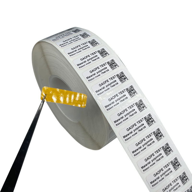
Evaluating Face Stock Materials for Circuit Board Labels
Polyimide (Kapton) Labels for High-Heat Processes
Polyimide serves as the industry standard for high-heat environments. It handles direct soldering environments with ease. You apply it to both the top and bottom sides of the board before the SMT process begins. Dimensional stability remains its strongest attribute. Polyimide resists shrinking, curling, or yellowing under extreme thermal stress.
The molecular structure of polyimide prevents it from breaking down during the thermal soak and peak reflow stages. This stability keeps barcodes perfectly proportioned. Scanners cannot read distorted or shrunken 2D codes. Polyimide ensures the physical dimensions of the printed matrix remain identical before and after the oven. Engineers typically specify 1-mil or 2-mil thick polyimide films. The 1-mil option offers better conformability on uneven surfaces, while the 2-mil option provides higher rigidity for automated dispensing.
Polyester (PET) Labels for Post-Process Application
Polyester offers distinct advantages but carries strict thermal limitations. PET typically fails when temperatures exceed 150°C. It shrinks, warps, and melts in reflow ovens. Attempting to pass a polyester label through a lead-free reflow profile results in complete material destruction and potential oven contamination.
Position PET strictly as a cost-effective alternative for post-process application. Use it for final packaging identification or chassis tracking. Apply it to components never subjected to reflow heat, such as large electrolytic capacitors or connectors added during final hand assembly. When utilized correctly in the post-solder phase, polyester provides excellent tear resistance and durability.
ESD-Safe (Anti-Static) Materials
Electrostatic discharge poses a massive threat to sensitive electronic components. Removing a label from its release liner generates static electricity through triboelectric charging. This sudden voltage spike can destroy microprocessors, memory chips, and other static-sensitive devices before the board even leaves the factory.
ESD-safe materials utilize static-dissipative adhesives and specialized face stocks. They prevent static buildup during application. These materials ensure the surface resistance remains within safe parameters, typically between 10^6 and 10^9 ohms. Implementing ESD-safe labels is mandatory when identifying components highly susceptible to electrostatic damage, ensuring compliance with ANSI/ESD S20.20 standards.
| Material Type | Max Temperature Resistance | Primary Application Phase | ESD-Safe Option Available |
| Polyimide (1-mil) | Up to 300°C (Short term) | Pre-Reflow / SMT Assembly | Yes |
| Polyimide (2-mil) | Up to 300°C (Short term) | Pre-Reflow / Auto-Apply | Yes |
| Polyester (PET) | Up to 150°C | Post-Process / Final Assembly | Yes |
| Paper / Direct Thermal | Up to 70°C | Shipping / Packaging Only | No |
Adhesive Formulations and Surface Energy
High-Tack Acrylic Adhesives
FR-4 boards and solder mask coatings present challenging surfaces for adhesion. They often possess low surface energy (LSE), typically measuring below 38 dynes/cm. Standard adhesives fail to grip these surfaces effectively. High-tack acrylic adhesives bite into these substrates aggressively. They form a strong initial bond that cross-links and cures rapidly upon application.
The concept of "wet-out" time dictates how quickly the adhesive flows into microscopic surface pores. Proper wet-out ensures the label resists chemical ingress during high-pressure board washing. If the adhesive fails to wet out completely, cleaning chemicals penetrate the bond line through capillary action. This causes the label edges to lift, eventually leading to complete detachment during the wash cycle. Engineers must specify adhesives formulated specifically for LSE plastics and textured solder masks.
Outgassing and Contamination Risks
Vacuum environments and high heat trigger adhesive outgassing. Volatile organic compounds (VOCs) escape from the adhesive layer when subjected to thermal stress. These gases condense on nearby surfaces as they cool. They contaminate delicate solder joints, optical components, and sensitive sensors.
Aerospace, military, and medical device PCB assembly mandate low-outgassing adhesive formulations. Standard adhesives release too many volatile compounds, risking catastrophic failures in sealed environments. Specifying low-outgassing acrylics prevents this contamination and ensures compliance with strict industry standards like ASTM E595, which requires a Total Mass Loss (TML) of less than 1.0%.
Printing Technologies for High-Resolution PCB Labels
Thermal Transfer vs. Direct Thermal
Direct thermal printing relies on heat-sensitive paper to produce an image. Passing these labels through a reflow oven turns the entire surface completely black. This renders all barcodes unreadable and destroys traceability instantly. Direct thermal printing has zero application in pre-reflow PCB manufacturing.
Thermal transfer remains the only viable technology. It utilizes a heated printhead to melt ink from a ribbon onto the face stock. This method produces high-contrast, high-density 2D barcodes on miniature labels. It supports the precise edge definition required for DataMatrix and QR codes, ensuring reliable scanning by automated equipment. For micro-labels, facilities often upgrade to 600 dpi printheads to maintain crisp module edges on codes smaller than 5mm.
Selecting the Right Thermal Transfer Ribbon
The choice of thermal transfer ribbon directly impacts print durability. Ribbons fall into three main categories: wax, wax/resin, and full resin. Wax ribbons melt at low temperatures and smear easily under light abrasion. Wax/resin blends offer moderate durability but fail rapidly when exposed to harsh cleaning chemicals.
You must select ultra-durable, chemical-resistant full resin ribbons for PCB labels. Full resin formulations require higher printhead heat but deliver unmatched resistance. The print withstands aggressive flux cleaning, saponifiers, and ultrasonic baths. It also survives conformal coating processes without degrading or bleeding into the surrounding board area. Matching the specific resin formulation to the polyimide topcoat is a mandatory step for permanent ink anchorage.
Scalability: SMT Workflow and Automation Compatibility
Design for Manufacturing (DFM): PCB Layout for Labeling
Design for Manufacturing starts at the CAD level. Engineers must design dedicated, flat "keep-out" zones on the bare board. These zones accommodate the physical dimensions of the label safely. Treating the label as a physical component during the design phase prevents placement conflicts on the assembly line.
Never place labels over vias or test points. Avoid proximity to component pads. Adhesive bleed during reflow can interfere with solder paste deposition. It can also alter local reflow profiling by acting as a thermal insulator. Clean, flat fiberglass surfaces provide the best foundation for permanent adhesion. Ensure fiducial marks remain clear of the label zone so AOI cameras maintain proper registration.
Auto-Apply vs. Manual Placement
High-volume production relies on automated label application. SMT label feeders present the material directly to pick-and-place machines. This automation requires specific material setups. The release liner plays a critical role in machine compatibility and dispensing reliability. The vacuum nozzle on the placement head requires a perfectly flat label presentation.
Glassine liners work well for manual application and standard desktop printers.
PET (polyester) liners prevent web breaks during high-speed automated dispensing.
PET liners ensure consistent tension through the feeder mechanisms.
Automated systems require exact gap sensing between labels for precise registration.
Peel plates on SMT feeders require stiff liners to snap the label away cleanly.
Label Size and Tolerance Constraints
PCB miniaturization drives the demand for micro-labels. Sizes routinely drop to 3mm x 3mm to fit on densely populated boards. Tight die-cutting tolerances become critical at this scale. A variance of even 0.1mm can cause the pick-and-place nozzle to miss the label center, resulting in dropped labels or skewed placement.
Poor die-cutting tolerances cause misfeeds in automated equipment. The adhesive can ooze from the edges, jamming the feeder mechanism. Precision rotary die-cutting ensures each label dispenses flawlessly. The matrix removal process during manufacturing must leave perfectly clean edges to support high-speed SMT placement without adhesive stringing.
Implementation Risks and Mitigation Strategies
Risk: Loss of Barcode Readability
Barcode degradation halts traceability and forces manual rework. Printhead failure, incorrect heat settings, or mismatched ribbons cause poor print quality. Excessive heat causes ribbon bleed, making barcodes unreadable. Insufficient heat leads to poor ink anchorage, causing the print to flake off during washing.
Implement inline barcode verification systems post-print and post-reflow. These systems grade the barcode against ISO/IEC 15415 standards in real-time. Ensure proper heat and darkness settings on the thermal transfer printer. Conduct regular printhead maintenance with isopropyl alcohol to prevent dead pixels from destroying 2D matrix data.
Risk: Label Flagging or Detachment
Label edges lifting trap chemicals and lead to complete detachment. This occurs when the adhesive fails to bond with the substrate. Surface contamination, insufficient wet-out time, or chemical incompatibility drive this failure mode.
Ensure boards are completely free of oils and particulates prior to application if applied post-wash. Verify the adhesive rating matches your specific chemical wash profile. Allow sufficient dwell time for the adhesive to cure before subjecting the board to high-pressure aqueous cleaning or ultrasonic baths. Test the wash profile offline before committing to full production runs.
Risk: OEM and Contract Manufacturer (CM) Misalignment
Contract manufacturers sometimes substitute cheaper materials to cut costs. A CM might replace a high-temp polyimide with a standard polyester, resulting in catastrophic failure during reflow. Vague documentation allows these unauthorized substitutions to occur unnoticed until production halts.
Explicitly define all label specifications in the Bill of Materials (BOM). Detail the exact face stock material, adhesive formulation, resin ribbon type, and placement coordinates in the assembly drawings. Mandate that any material deviation requires formal engineering approval from the OEM and update the Approved Vendor List (AVL) accordingly.
Risk: Inventory and Shelf-Life Degradation
Adhesives degrade over time. Exposure to extreme heat or humidity accelerates this degradation. Expired adhesives suffer from cold flow or lose their tack entirely, leading to flagging and detachment on the assembly line. Poor storage practices waste expensive materials and cause production delays.
Document proper storage conditions for all labeling materials. Maintain storage environments at 22°C with 50% relative humidity. Keep materials in their original protective packaging, sealed in poly bags, until required on the floor. Enforce strict FIFO (First-In, First-Out) inventory management to prevent using expired stock.
Conclusion
Standard labels represent a false economy in electronics manufacturing. Investing in polyimide thermal transfer labels is mandatory for reliable SMT traceability. Categorize your needs based on application timing and application method to narrow down material choices effectively.
Request physical material samples to conduct inline testing on your specific SMT equipment.
Perform in-house thermal profiling and chemical wash evaluations to verify adhesive performance.
Consult with a labeling specialist to match high-durability resin ribbons to your chosen face stocks.
Update your Bill of Materials (BOM) with exact material specifications to prevent unauthorized CM substitutions.
Designate specific keep-out zones for labels in your next CAD layout to improve DFM.
FAQ
Q: What temperature can polyimide circuit board labels withstand?
A: Polyimide labels withstand short-term exposure up to 300°C during lead-free reflow and wave soldering processes. For long-term continuous exposure, they maintain dimensional stability and adhesive integrity at temperatures around 150°C. This exceptional thermal resistance prevents shrinking, curling, or melting in harsh manufacturing environments.
Q: Can I use standard polyester labels for reflow soldering?
A: No. Standard polyester (PET) labels melt, shrink, and warp when exposed to temperatures above 150°C. Lead-free reflow ovens routinely exceed 260°C. Using PET during reflow destroys the barcode and contaminates the oven. Restrict polyester labels strictly to post-process applications or components not subjected to high heat.
Q: What is the best printing method for PCB labels?
A: Thermal transfer printing is the only viable method for high-reliability PCB identification. You must use high-durability, full resin ribbons paired with a compatible face stock. This combination ensures the printed barcode resists extreme heat, aggressive flux removers, and the abrasion of inline aqueous washing systems.
Q: What makes a circuit board label ESD-safe?
A: ESD-safe labels utilize static-dissipative face stocks and specialized adhesives. These materials prevent the buildup of static electricity when the label is peeled from its release liner. By keeping surface resistance within safe parameters, they protect sensitive electronic components from catastrophic voltage spikes during application.
Q: Why do my PCB labels fall off during the chemical wash?
A: Labels detach due to incompatible adhesives, insufficient cure time, or poor surface wet-out. High-pressure aqueous systems and harsh saponifiers attack weak bond lines. Ensure you use high-tack acrylic adhesives designed for low surface energy (LSE) boards and allow proper dwell time before washing.
Q: Can circuit board labels be applied automatically?
A: Yes. High-volume manufacturing utilizes SMT label feeders and pick-and-place machines for automated application. This requires labels engineered with tight die-cutting tolerances and specific release liners. PET (polyester) liners are highly recommended to prevent web breaks and ensure consistent tension during high-speed dispensing.


